Welcome to our site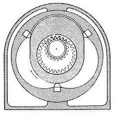  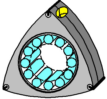 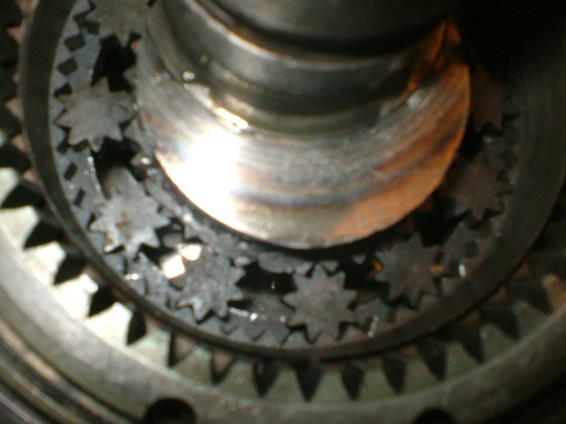 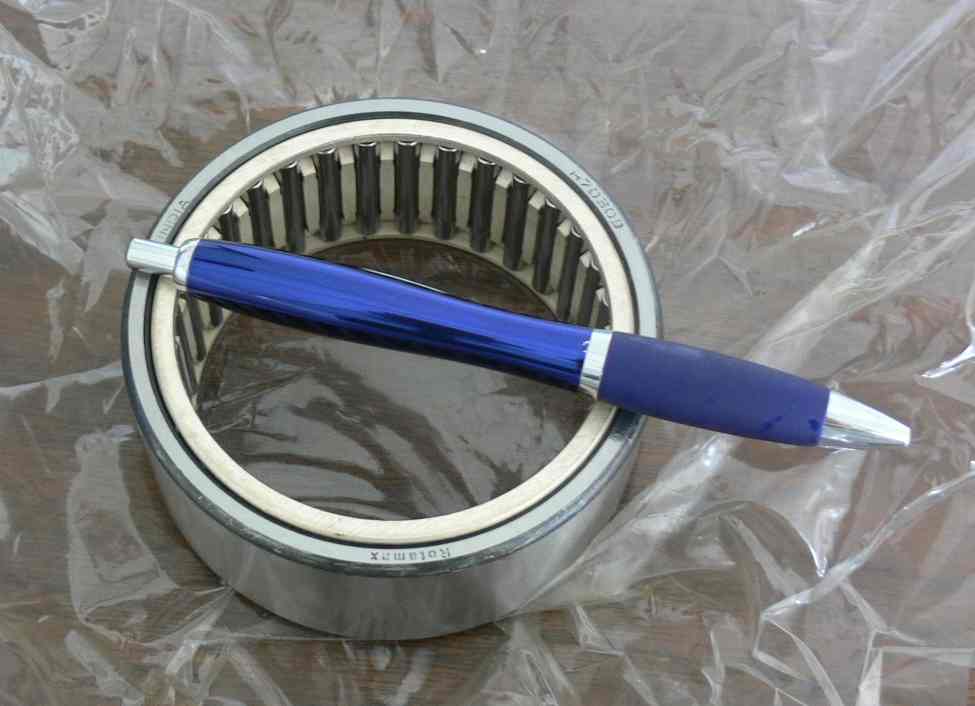 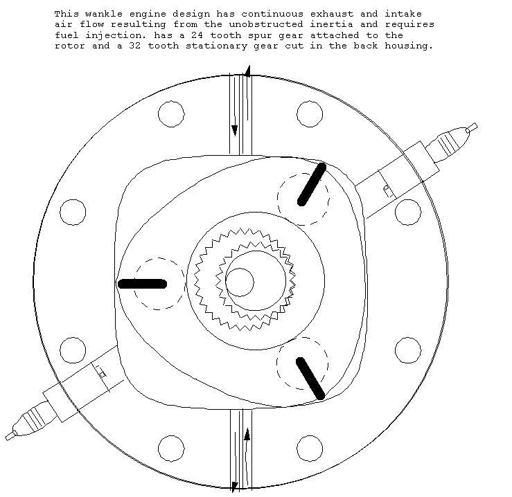 |
||
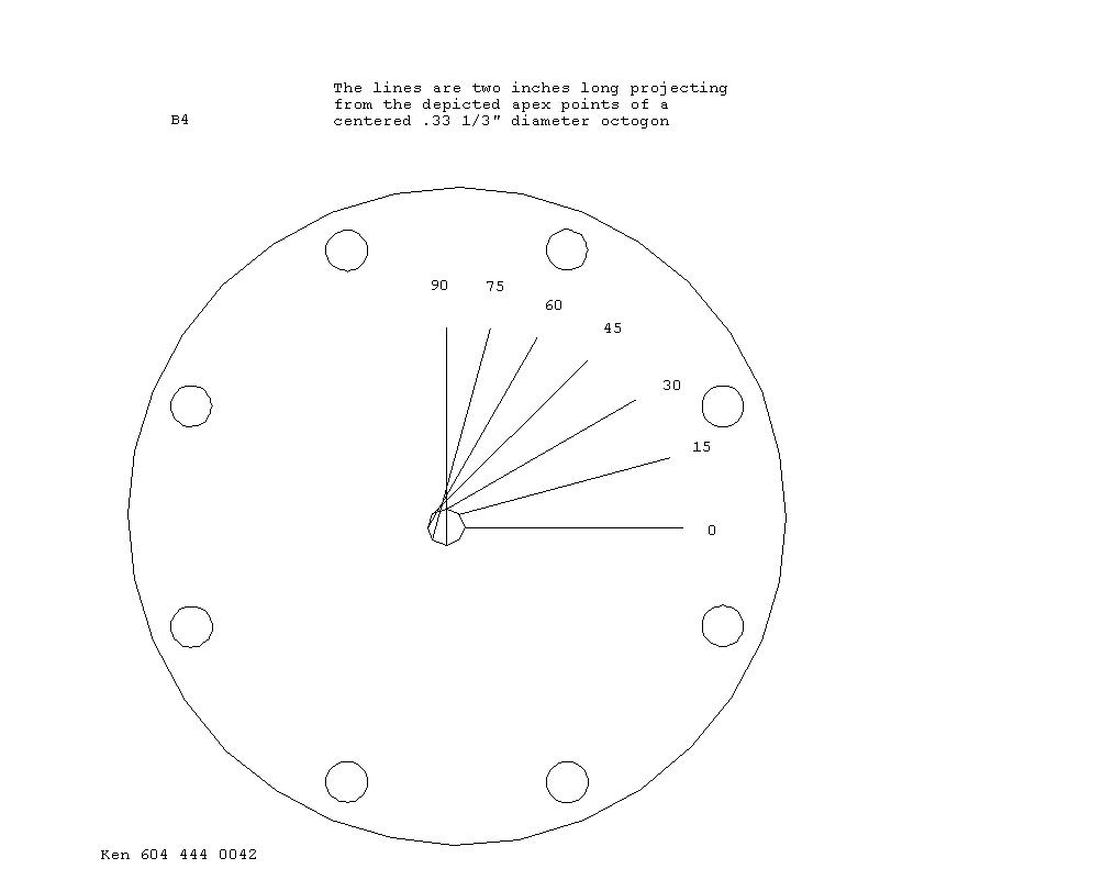
Above could be the best Steam, water, air, and gasoline engine design that is found in the world.. The design was made on December 22, 2011. The design consists of using the same gear ratio as the Wankel engine with the spur gear attached to the rotor and the interior gear cut into the housing. The e-shaft rotates once clockwise and the rotary piston rotates one and a half revolutions counter clockwise. DRAWING INSTRUCTIONS Draw a stationary 1.5" diameter nine sided polygon in the center of the page with the one veritical surface to the left hand side. Draw a 1" diameter six sided polygon that has the right and left sides vertical. Center a 3.5" vertical line at center then shift the line and 6 sided polygon 1/4" to the left. (Polygon Line) Make a small mark at both ends of the line. Rotate the line 20 degrees counterclockwise and fit it to the next clockwise surface and put small marks at both ends of the line. Repeat the aforesaid seven more times. Draw a curved line between the marks to show the housing profle. Put the polygon line at the start point and measure from it to the left hand side of the housing. choose a semi circle size to almost meet the housing and both ends of the polygon line. make an exact copy of the line and paste it on the right hand side. Play with it to understand port and or sparkplug locations and appreciate the power available from the counter rotating parts. it should be noted that the rotor combustion suface alternates. Note that the two apex seals make it so that the port and sparkplug positions can be positioned where there is minimium pressure and vacuum loss. The spur gear of a prototype is made by using .14" diameter diagional square at center shifting it up .57" then remove the top half then repeat it around to make 24 teeth. The Stationary gear is made shifting the diagonal square .82" and repeat around to make 36 teeth. I have 20 sets. Just email me. The e-shaft eccentric has to be outside of the housing in this design or have only a 3/8" drive shaft on one side.of the engine. THIS DESIGN IS NOT AN ORPHAN. The three sided rotor has a different gear ratio to the Wankel engine. Ken On top is the Grandfather of rotary designs. The Cooley engine U.S. patent number 748384 dated December 29 1903 Note that the large interior gear is centered in the housing and the small spur gear is centered on the rotor. Followed by directions to draw the Wankel housing profile. In trying to understand centrifugal forces one has to spin a one pound weight around a one foot radius once per second to understand that it is equal to gravity. Divide one foot pound by 86,400 the seconds in a day then multiply the sum times 5,280 to get foot pounds per mile, then multiply this times 3800 the radius of the earth to fine that if the earth does spin on its axis once a day and find that a 230 pound man standing on one of the poles would levitate when standing on the equator. Or calculate the speed of the moon to encircle the earth daily and create the tides and find that it travels 100.000 times the speed of sound. Followed by a sketch showing the size of the rollers required for minimum friction between the e-shaft journal and rotor. Followed by a rotor with meshing gears to confirm the size if the rollar gears. Followed by the wrong size rollars in an aircraft rotary engine that failed. |
||